 Input/Output
GPIO
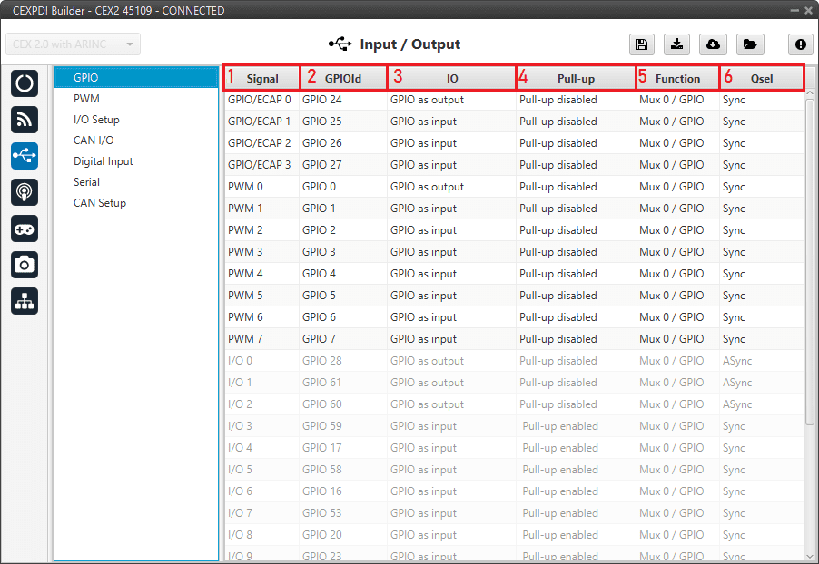
In this panel users can configure each individual GPIO behavior:
GPIO panel
Signal: Pin ID as described in Hardware installation - Pinout section of the CEX Hardware Manual.
GPIOId: GPIO ID of the microcontroller.
IO: Define GPIO as an input or ouput.
Pull-up: Enable or disable the pull-up resistance.
Function: Mux 0/GPIO: GPIO, Mux 1: PWM, Mux 2 or Mux 3. These are the different functionalities that the GPIO can have, depending on the multiplexer.
Qsel: This is the “input qualification”, it is used to control how the value of a GPIO is evaluated. The available options are:
Sync: The value is taken as whatever is present at the time it is checked (synchronously). This is the default mode of all GPIO pins.
3 Samples: The value is checked 3 times and the value is only changed when the 3 times are the same.
6 Samples: Same as before, but checking 6 times instead of 3.
ASync: No checks are performed. It is used when it is not used as GPIO.
PWM
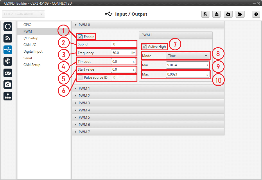
In this panel, each PWM can be configured:
PWM panel
Note
PWMs in CEX work in normalized mode, so when the input value is 0 the output value will be the minimum configured, and when the input value is 4095 (12 bits all with ones), the output will be the maximum configured. This approach allows usage of the maximum resolution for the commanded value.
The configuration parameters are:
Enable: Define if the PWM is enabled or not.
Note
This checkbox disables the pin as GPIO and enables it as PWM. Hence, in the GPIO menu the “Function” parameter shall change to “Mux 1”.
Sub id: Identifies the sub-id of the PWM and, according to this value, determines the command to be used, using one type of CAN message or another.
Frequency: PWM output frequency.
Timeout: If a PWM message is not received in less than this time, the PWM will output the start value.
Start value: Value used before any PWM message arrives and on timeout.
Pulse source ID: PWM input ID [0,3], defined in the Digital Input panel.
Active High: Polarity high or low (high if enabled).
Mode: The available options are Time and Duty cycle.
Time: The values indicated in Min and Max parameters are expressed in time units.

Time units
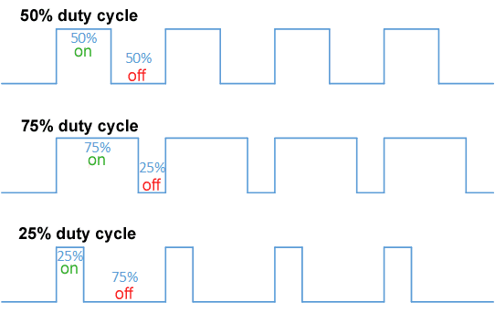
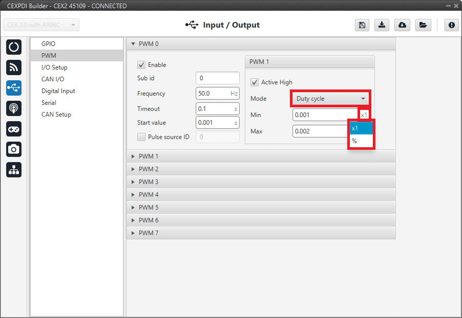
Duty cycle: This option is a a different way of indicating the pulse width. Now the value indicated in Min and Max parameters is a percentage which corresponds to the relation between the pulse width over the total period of the sent signal.
So a 100% duty cycle will correspond to a signal with a constant value of 1, while a 0% duty cycle implies a constant signal with value 0. Between this two extremes, the pulse width can vary as in the examples shown in the following figure.
Duty cycle
Min: This parameter is the pulse width value that will make the servo/actuator go to its lowest position.
It will be the output when the PWM message specifies 0.
Max: This parameter is the pulse width value that will make the servo/actuator go to its highest position. It will be the output when the PWM message specifies 4095.
An example of reading PWM can be found in Commanding/Reading PWMs - Integration examples section of the present manual.
I/O Setup
In this panel the user can establish the relationship between a determined signal with a I/O port. This allows users to configure serial inputs and outputs: external sensors, custom messages, etc.
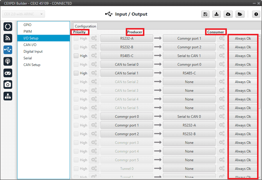
I/O Setup panel
Priority: Connections between I/O ports can be marked with high priority with this checkbox. If enabled, they will run at high frequency: 1000 Hz.
Producer: Functions for creating and sending messages.
Consumer: Functions for receiving and parsing messages.
Bit: This assigns each connection to a bit. Thus, the connection is activated/deactivated depending on the status of the selected bit. By default, the Always Ok bit is set to all connections so that they are always active.
The following are the steps to setting up reception or transmission between ports:
Choose the Producer to use.
To configure the desired Consumer that will be bind to the chosen Producer, it is first required to establish the relationship between them:
Bind \(\rightarrow\): Unidirectional relationship.
Bind Bidirectional \(\leftrightarrow\): Bidirectional relationship. This enables a port to receive or send information.
Note
Once the Consumer has been selected, it is possible to undo the selection by pressing the Clear button.
Select the desired Consumer element.
(optional) Configure the Bit parameter. By pressing on the bit button, the user can select the bit to assign the connection to.
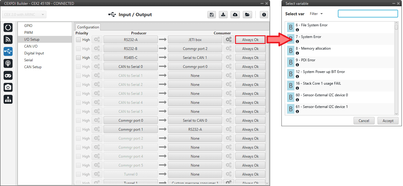
Bit - Select a variable
The following I/O ports are available:
Field |
Description |
|---|---|
RS232-A |
Serial Port 232 A |
RS232-B |
Serial Port 232 B |
RS485-C |
Serial Port 485 |
Commgr port |
COM Manager ports send and receive VCP messages. This is the protocol used by Veronte products to communicate. For more information, read the VCP user manual |
Tunnel |
Creates a bidirectional brigde between two devices, see Tunnel |
Custom message producer/consumer |
This allows user to send/receive a serial custom message, see Custom message |
Y splitter producer/consumer |
Used to split a signal into 2 |
CAN to Serial / Serial to CAN |
Serial to CAN sends serial streams over a CAN Bus / CAN to serial undoes the transformation ‘Serial to CAN’ |
CAN wrapper for serial transmission / Serial CAN unwrapper |
CAN wrapper for serial transmission sends CAN streams over a serial Bus / Serial CAN unwrapper undoes this transformation. For more information on these ports, please refer to CAN wrapper/CAN unwrapper - Input/Output section of the 1x PDI Builder user manual |
Tribunus ESC |
Reads telemetry data from the Tribunus ESCs by connecting it to one of the serial ports |
Lift - MCU |
Created for communication with a Lift MCU |
JETI box |
Simulates a Jetibox to read telemetry from legacy Jeti devices, see JETI box |
JETI telemetry |
Reads telemetry from Jeti devices |
ARINC producer channel/consumer |
This allows user to send/receive ARINC 429 messages through HI-3210, see ARINC communication protocol |
More information about some elements can be found in the following sections.
Tunnel
It is possible to configure a Tunnel which is a bidirectional bridge between units that communicate to each other sharing information about an external device connected to the Serial or Digital port.
Let’s consider the following image.
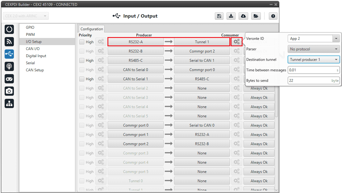
Tunnel configuration
In the image above there is a device connected to the RS232-A (Producer) and there is a Tunnel (Consumer) which sends that information to Veronte applications (App 2). On the other hand, a Veronte application, for example Veronte Ops, will receive the signal sent by this CEX unit.
The option available when configuring Tunnel as Consumer are:
Veronte ID: Enter the address that will receive the information. The following options are the most common:
App 2: Veronte applications address.
Broadcast: All units on the network. Select this option for a generic configuration.
Address of a specific Veronte unit, it can be a 1x, a 4x, a CEX, etc.
For more information on the available addresses, see List of addresses section of the CEX Software Manual.
Parser: The user can choose protocol to parse message data. The options available are:
No protocol
RTCM3
CANserial
Destination tunnel: Number of port is used to avoid mistakes and identify a Tunnel when using more than one, Tunnel 0, 1 and 2 are available.
Time between messages.
Bytes to send: Sets the message size to send.
When configuring Tunnel as Producer (i.e. on the unit that receives the information), no configuration is required. It is only necessary to connect it to a Consumer, usually to a serial port.
Custom Messages
Warning
CEX has a serial limitation shared with all Custom Messages:
Maximum number of vectors (fieldset): 100
Maximum number of fields: 1000
Each Custom message consumer has a limit of 32 fields.
It is possible to configure the messages sent/received through the serial port and its conversion to system variables by selecting the option Custom message producer/consumer and configuring the I/O port.
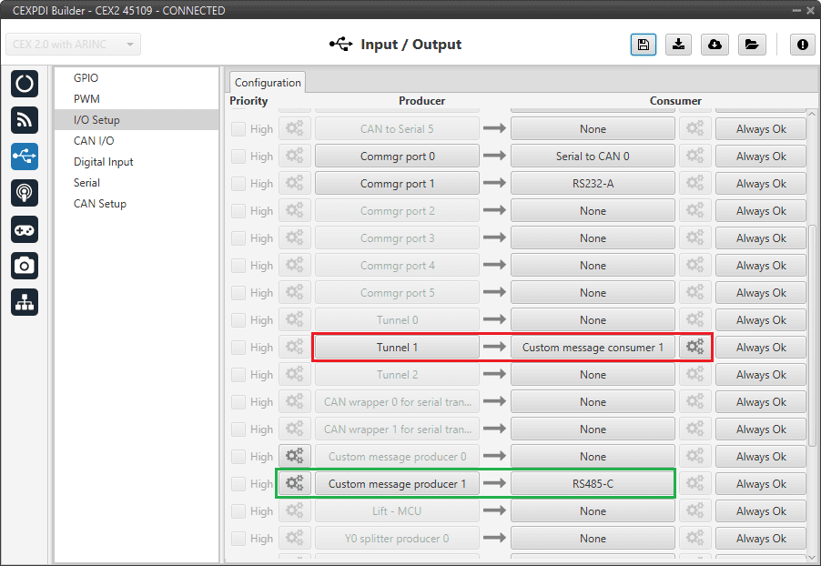
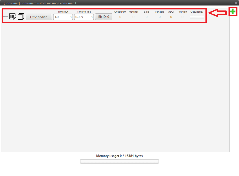
Serial Custom Messages
In the image above can be seen two possible configurations using a Custom Message. The ‘red’ one is configured to receive a determined message from Tunnel 1 and the ‘green’ is used to send a Custom Message through a RS-485 serial port. It is also possible to use the same Custom Message for both tasks if the bidirectional relationship is selected (the arrow indicates this, \(\leftrightarrow\)).
To configure a Custom message, the user must follow the next steps:
Press the configuration button (
 icon) and another window will be displayed. In this window press the “+” icon to add a custom message.
Serial Custom Message configuration
When it is already added, the following options are available to configure a custom message:
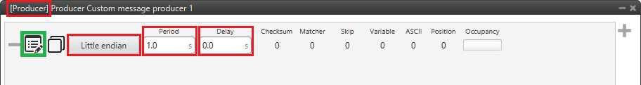
Custom Message producer configuration
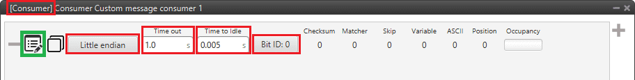
Custom Message consumer configuration
Endianness: Depending on the order in which the device issue the message, it is possible to select:
Big endian: Set the value from left to right.
Little endian: Set the value from right to left.
Mixed endian: Some devices use this format. If users need to configure it, please contact the support team (create a ticket in the customer’s Joint Collaboration Framework; for more information, see Tickets section of the JCF manual).
Period/Time out: This option has a dual role depending on if it is used to transmit or receive data.
Period - Producer: It is the inverse of the send frequency.
Time out - Consumer: This is the threshold time between receptions to consider that the message is not being received correctly.
Delay/Time to Idle: This option has a dual role depending on if it is used to transmit or receive data.
Delay - Producer: It is a delay applied before sending the message. This serves to send messages with the same period without overloading the Serial bus.
Time to Idle - Consumer: This is the time CEX waits before discarding partially parsed bytes.
Bit ID: This option is only available when a message is configured as Consumer. The user bit selected in Bit ID box will be true if the message is being received correctly.
Warning
Pay attention that the user bit selected in Bit ID is not in use for another task.
To create the structure of the message, click on the edit message button (
 icon) and then press the “+” icon to add fields to it. The following type of messages are available to configure a structure: Variable, Checksum, Matcher, Skip and Parse ASCII. The configuration of each structure is covered in the Custom Messages types - Input/Output section of the 1x PDI Builder manual.
Warning
Before configuring any message, user has to know the structure it has to have according to the device that is connected to the port. Each device may have a different message structure when it sends or receives information.
JETI box
JETIBOX is a universal communication terminal which can be used with any JETI products.
JETIBOX operates as a two-way terminal, showing all data stored in the JETIBOX Compatible product. With the use of four buttons, the user can browse the menu and set the selected values to take advantage of the full capability of JETIBOX Compatible products.
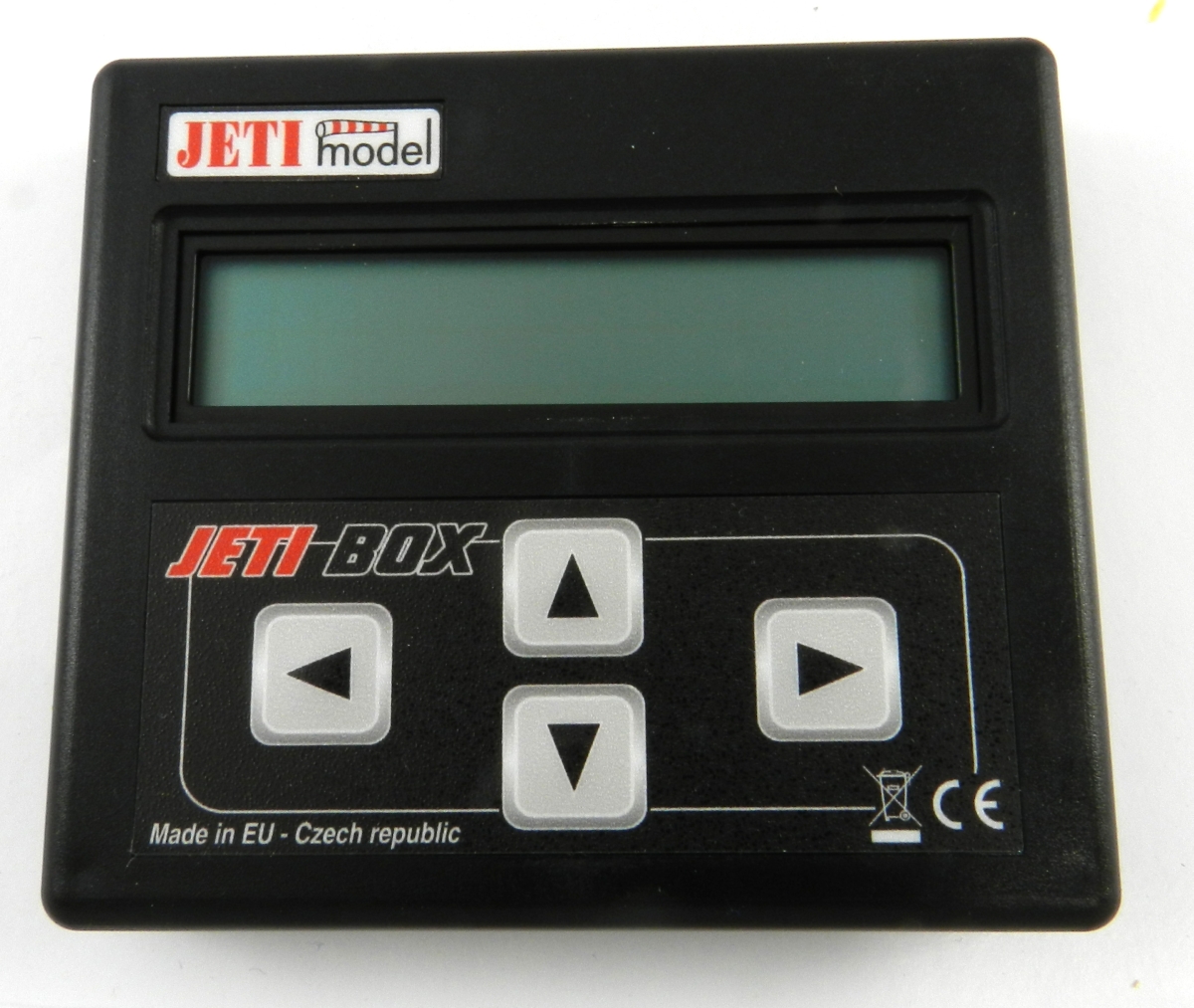
JETI box device
To simulate it, it is necessary to link the specific JETI box IO consumer to a serial port:
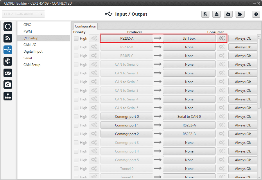
JETI box Consumer
Then, the sequence to retrieve the data shall be configured by clicking on the configuration button ( ![]() icon):
icon):
To add a Custom Message, just click on the “+” icon:
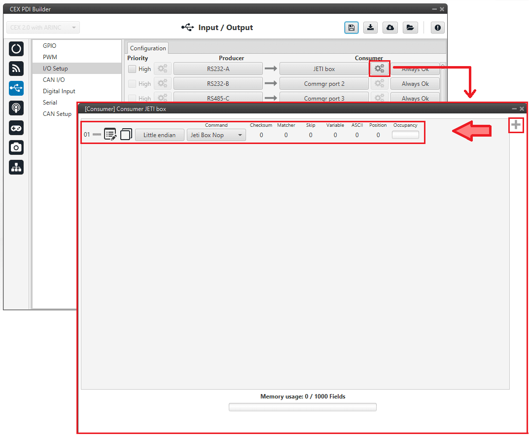
JETI box Configuration
The following parameters can be configured in this pop-up window:
Endianness: Depending on the order in which the device issue the message, it is possible to select:
Big endian: Set the value from left to right.
Little endian: Set the value from right to left.
Mixed endian: Some devices use this format. If users need to configure it, please contact the support team (create a ticket in the customer’s Joint Collaboration Framework; for more information, see Tickets section of the JCF manual).
Command: Here the user can select between Jeti box Left, Jeti box Down, Jeti box Up, Jeti box Right or Jeti box Nop. These correspond to the four buttons on the physical JETIBOX (see image above), except the Jeti box Nop that is only for simulating a “wait”.
For example, to read the Actual Voltage of a Jeti MasterSpin 220 the Consumer must be configured with a series of custom messages (use Big endian in all messages).
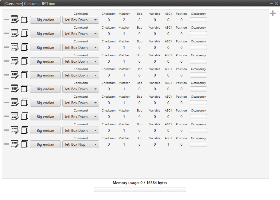
JETI box example
Below is a small example with the configuration of one of these messages, the full example can be found in Jetibox - Integration examples section of this manual.
Expected text: “CONTROLLER TYPE MasterSpin 220~”
Command: Jeti box Down
Matcher(32) “CONT” 0x434F4E54 (1129270868)
Skip(24*8) 192
Matcher(32) “220~” 0x3232307E (842150014)
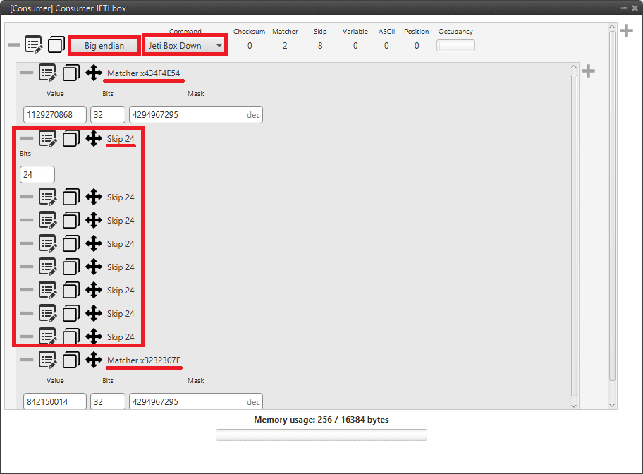
JETI box custom message example
ARINC communication protocol
CEX supports the reception and sending of information following the ARINC 429 communication standard. ARINC 429 messages consist of a 32-bit sequence as shown below.
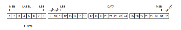
ARINC message - Bit sequence
1 - 8: The label/status byte.
9 - 10: Source Destination Identifier (SDI) bits. SDI function is used when specific messages need to be directed to a specific system of a multi-system installation.
11 - 31: Data bits.
32: Parity bit. Parity is a method of detecting errors in transmission.
The following configuration must be carried out in CEX PDI Builder for enabling reception and transmission of ARINC messages.
ARINC message reception
Go to Input/Output \(\rightarrow\) I/O Setup panel \(\rightarrow\) Configuration tab.
Connect an ARINC producer to a Custom message consumer.
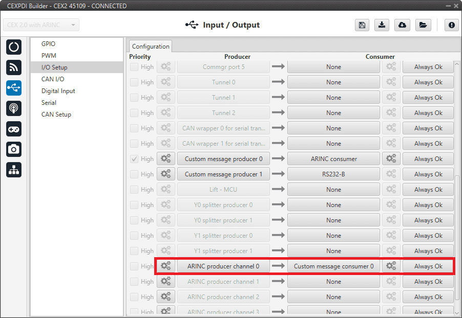
I/O Setup - Producer selection
Configure the ARINC producer according to the message to read:
Low speed: Selects the transmission rate for the ARINC 429 transmit channel (low if checked, high if not).
Parity check: When this parameter is checked, the 32nd received ARINC bit is overwritten with a parity flag. The flag bit is set to a zero when the received ARINC word, including its parity bit, has an odd number of ones. Contrarily, when this parity check is not ticked, all 32-bits are received without parity checking.
SDI filter: Once this parameter is checked, SDI function is enabled. Users must configure the identifier of the ARINC messages to read (0, 1, 2 or 3) corresponding to the decimal value of SDI bits.
Note
The decimal value is extracted from the binary number formed by bits 10 and 9 in that order.
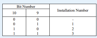
SDI bits - ID numbers
Enabled labels: Users can set the labels of the ARINC messages to read, by selecting the corresponding decimal value of Label bits.
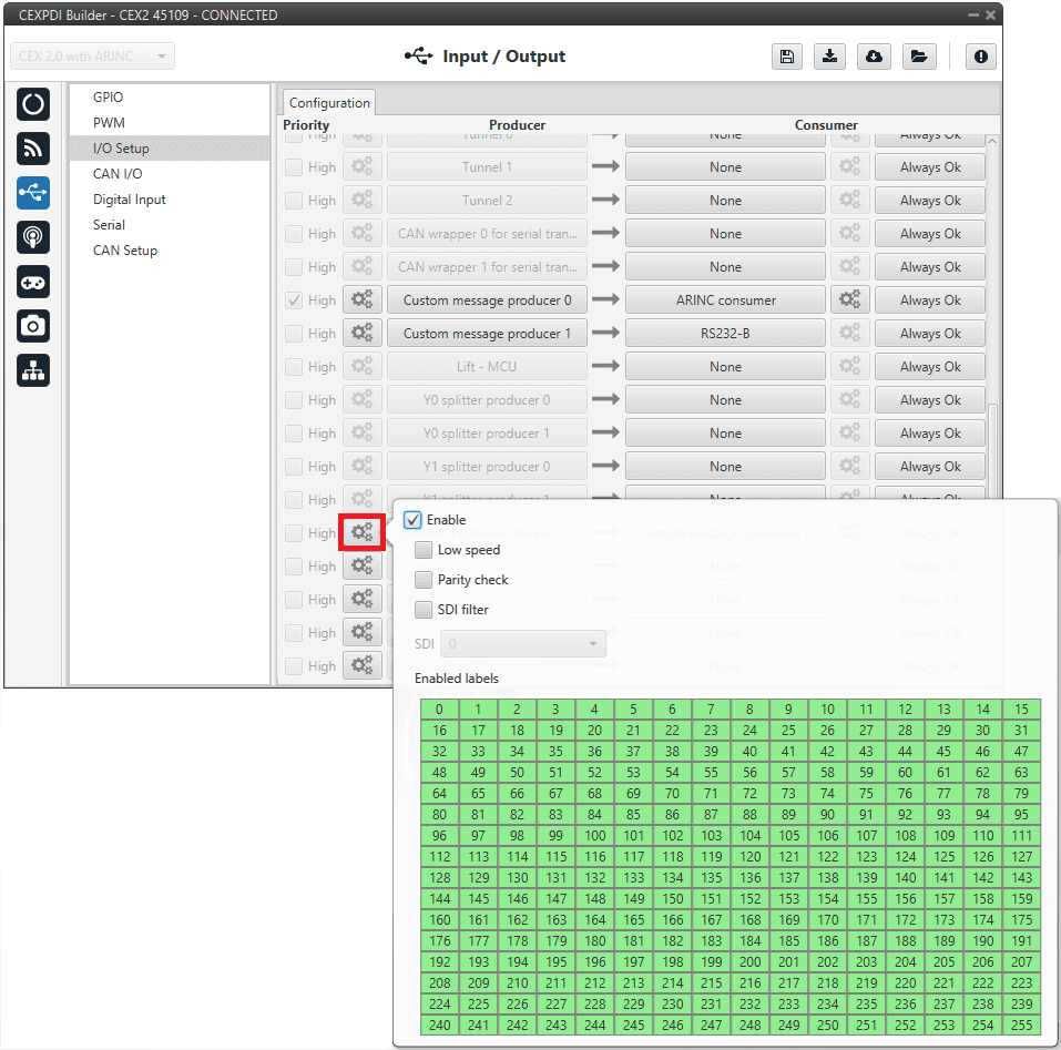
I/O Setup - ARINC Producer configuration
Configure the Custom message consumer as follows:
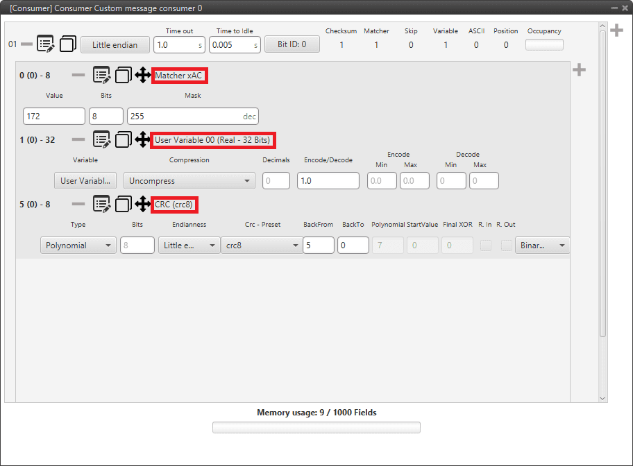
I/O Setup - Consumer configuration
In order to ensure proper communication, it is mandatory to follow the structure above, adding a Matcher in the beggining, then a Variable (or variables corresponding to the 32 bits of the ARINC message) and a CRC at the end of the Custom message with the following values for the parameters:
Matcher:
Value: 172
Bits: 8
Variable or variables: This must correspond to the 32 bits of the ARINC message that users wish to receive. These can be configured in several ways, as long as all bits are represented and there is no loss of data. That is, the ARINC message does not necessarily have to be configured as a 32-bit uncompressed variable such as the User Variable 00 shown in the example.
Checksum (CRC):
Type: Polynomial
Endianness: Little endian
CRC-Preset: crc8
BackFrom: 5
BackTo: 0
Binary mode
ARINC message transmission
Go to Input/Output \(\rightarrow\) I/O Setup panel \(\rightarrow\) Configuration tab.
Connect an Custom message producer to a ARINC consumer, and configure the consumer according the ARINC message to send.
Low speed: Selects the transmission rate for the ARINC 429 transmit channel (low if checked, high if not).
Parity check: When this parameter is checked, the 32nd transmitted ARINC bit is overwritten with a parity flag. Contrarily, when it is not, all 32-bits are transmitted as data.
Even: When the Parity check is ticked, this parameter defines whether the 32nd transmitted bit is set for Even or Odd Parity. Ticking the Even checkbox selects even parity, if not odd parity will be selected.

I/O Setup - ARINC Consumer configuration
Configure the Custom message producer as below. In this example, Relative Timestamp variable is being sent.
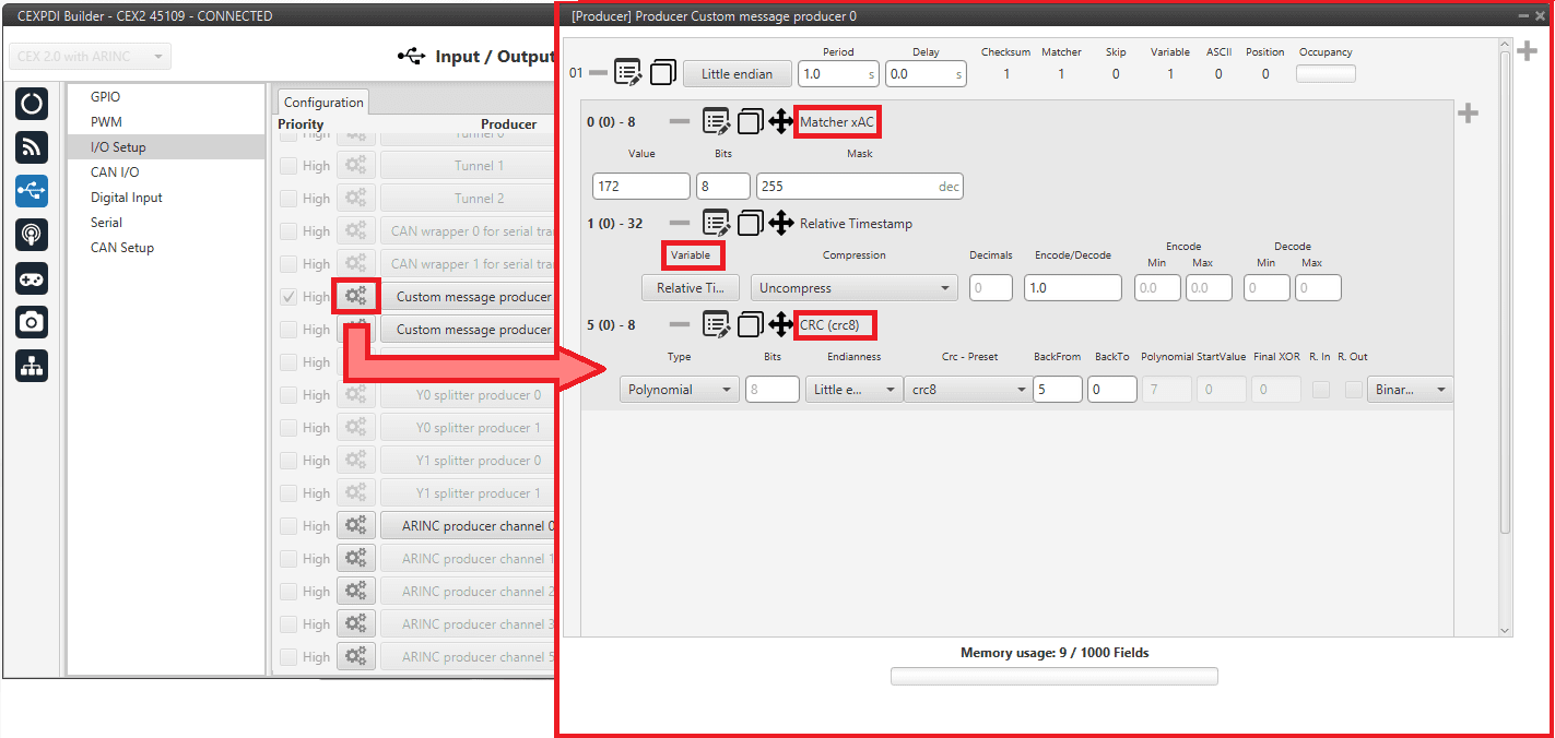
I/O Setup - Consumer configuration
In order to ensure proper communication, it is mandatory to follow the structure above, adding a Matcher in the beggining, then a Variable (or variables corresponding to the 32 bits of the ARINC message) and a CRC at the end of the Custom message with the following values for the parameters:
Matcher:
Value: 172
Bits: 8
Variable or variables: This must correspond to the 32 bits of the ARINC message that users wish to send. These can be configured in several ways, as long as all bits are represented and there is no loss of data. That is, the ARINC message does not necessarily have to be configured as a 32-bit uncompressed variable such as the Relative Timestamp shown in the example.
Checksum (CRC):
Type: Polynomial
Endianness: Little endian
CRC-Preset: crc8
BackFrom: 5
BackTo: 0
Binary mode
CAN I/O
Warning
Remember that for the reception of CAN messages, Mailboxes need to be configured accordingly.
A CAN (Controller Area Network) Bus is a robust vehicle bus standard widely used in the aviation sector. CEX is fitted with two CAN buses that can be configured independently.
The structure of a CAN message can be seen in the following image:
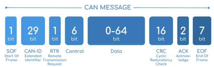
CAN message structure
Only the ID is introduced in the system, the rest of the message layout is already coded. The data field is the one build by the user to send, and parsed when received.
For more information on the CAN Bus protocol, see CAN Bus protocol section of the CEX Software Manual.
The baud rate of both CAN buses can be configured in the CAN Setup panel.
Configuration
This menu allows the configuration of the CAN inputs and outputs.
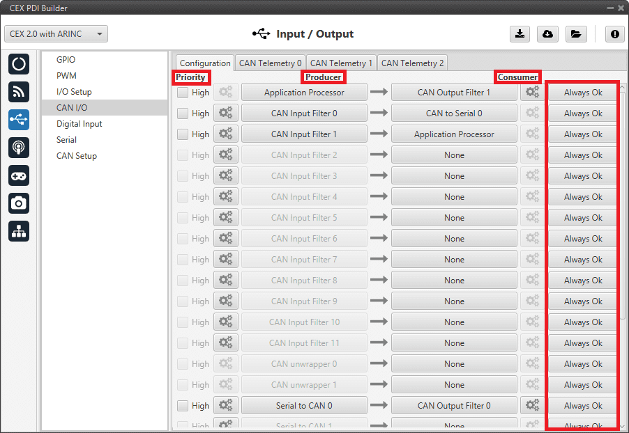
CAN I/O - Configuration panel
In this menu, the user can find the same ‘columns’ (Priority, Producer, Consumer and Bit) as in the I/O Setup panel. In addition, the process for configuring producers and consumers is also the same as described in the I/O Setup - Input/Output section.
Warning
In CAN, in Low state the specified period is not guaranteed but in High state it is.
However, only those messages that are critical for external devices should be set as high priority, as this may disrupt the proper functioning of Veronte CEX.
On the one hand, CEX has the producers shown below:
Application Processor: Sends a specific set of information, the “status message”. This message is composed as: version (major, minor and revision), address (serial number), system bit error, system power up bit error, PDI bit error, memory allocation bit, fily system bit error, CAN A bit error, CAN B bit error, arbiter enabled and arbiter status.
CAN Input Filter: CAN input filters. Those CAN messages received in one filter can no longer be received in subsequent filters. The following parameters need to be configured by clicking on the
icon: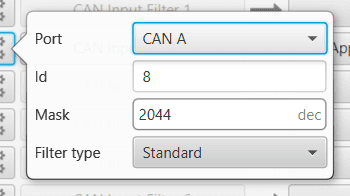
CAN Input Filter configuration
Port: It is required to configure the CAN bus from which it listens, the user can choose between CAN A, CAN B or BOTH.
Id: CAN Id must be set and it is used to identify messages. The value set has to be decimal format.
Mask: Here a CAN Id mask can be set to filter messages. The mask marks which bits of the message id (in binary) are matched.
For example, if standard Ids (11 bits) from 8 to 11 (100 to 111 in binary) want to be admitted, the mask should be set to binary 11111111100, i.e. 2044 in decimal.
Warning
Make sure that the mask is set properly to be able to receive the desired CAN messages.
The mask should be 11 bits for Standard frame format and 29 bits for Extended frame format.
More information about this can be found in How to create a mask - FAQ section of this manual.
Filter type: The options available are Standard (frame format with a 11-bit identifier), Extended (frame format with a 29-bit identifier) and Both.
CAN unwrapper: This undoes the ‘CAN serial wrapper’ action, it has to be connected to I/O Setup consumer (Serial CAN unwrapper).
Serial to CAN: Serial messages via CAN output, it has to be connected to I/O Setup consumer. It can be configured in the configuration button (
icon), a pop-up window will appear: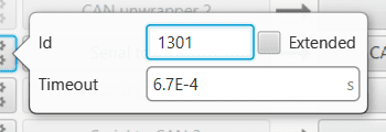
Serial to CAN configuration
Id: CAN Id must be set and it is used to identify messages. The value set has to be decimal format.
Extended: If enabled, the frame format will be this, ‘Extended’, i.e. with a 29-bit identifier. Otherwise, the frame format ‘Standard’ (11-bit identifier) is set by default.
Time out: This is the threshold time between receptions to consider that it is not being received correctly.
CAN Custom Producer Telemetry: Telemetry messages sent via CAN (such as CAN custom messages on Veronte Autopilot 1x). They are configured in the next section, see CAN Telemetry.
On the other hand, the consumers are the following:
Application Processor: Receives a specific set of information sent by Veronte Autopilot 1x or Arbiter.
CAN Output Filter: CAN output filters. The user can choose between CAN A, CAN B or BOTH in the configuration button (
icon).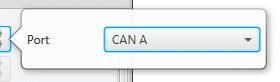
CAN Output Filter configuration
CAN serial wrapper: CAN messages via serial output, it has to be connected to I/O Setup producer (CAN wrapper for serial transmission).
CAN GPIO consumer: CAN messages from Autopilot 1x or Autopilot 4x for GPIO inputs. An example of how to implement it can be found in the GPIO Command - Integration examples section of the present manual.
CAN to Serial: This undoes the ‘Serial to CAN’ action, it has to be connected to I/O Setup producer.
CAN Custom Consumer Telemetry: Telemetry messages received via CAN (such as CAN custom messages on Veronte Autopilot 1x). They are configured in the next section, see CAN Telemetry.
CAN Telemetry
In the CAN Telemetry tabs (there are 3 available), the user chooses the telemetry to be sent/received via the CAN buses. The following elements can be configured:
TX Ini: Used to configure transmitted messages that are only sent once at the beginning of the operation (sent when CEX boots up). They can be used to initialize some devices.
TX: Used to configure transmitted messages.
RX: Used to configure the reception messages (where they are stored).
Warning
The maximum capacity of a CAN message is 64 bits (8 bytes), so to send more information it must be divided into several messages.
CEX has a CAN limitation of 40 TX Ini messages per Custom, 40 TX messages per Custom and 80 RX messages per Custom.
In addition, there is a limit shared with all Customs:
Maximum number of vectors (fieldset): 160
Maximum number of fields: 1280
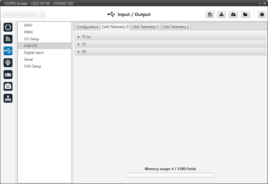
CAN I/O - CAN Telemetry panel
As this section works in exactly the same way as in the 1x PDI Builder software, the explanation on how to configure the telemetry messages via CAN is reflected in the Custom Messages - Input/Output section of the 1x PDI Builder user manual
An example of the sending of CAN telemetry messages can be found in the CAN communication - Integration examples section of this manual.
Digital Input
CEX digital signal inputs can be used to measure pulse count, pulse widths and PPM signals from a RC radio.
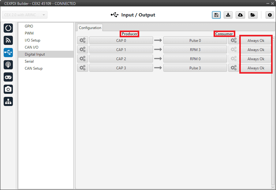
Digital Input panel
In this menu, the user can also find the same ‘columns’ (Producer, Consumer and Bit) as in the I/O Setup panel. In addition, the process for configuring producers and consumers is also the same as described in the I/O Setup - Input/Output section.
The process to configure a device can be done as follows:
Select and configure a Producer. There are 4 possible producers: CAP 0 - 3.
Press on the configuration button (
icon) and a new pop-up window will show.
Digital Input panel - Producer
The pop-up window contains the following configurable elements:
Enable: By ticking this checkbox, the corresponding producer is enabled.
Note
When enabling it, in the GPIO menu the “Function” parameter corresponding to this pin shall automatically change to “Mux 1”.
Warning
Please check that this change has been made.
CAP pin entry: Selects which pin this CAP is associated to and, therefore, to which the device is connected to.
Note
Pins are associated in the following way:
CAP 0 with GPIO/ECAP 0
CAP 1 with GPIO/ECAP 1
CAP 2 with GPIO/ECAP 2
CAP 3 with GPIO/ECAP 3
Edge detection: How the pulses are read and transformed into a digital signal (how they are processed).
By clicking on the drop-down menu, the following options can be selected:
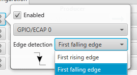
Digital Input panel - Edge detection option
First rising edge: With this option, when the rise of the pulse is detected, the data will start to be stored. Recommended when consumer is PPM or Pulse.
First falling edge: With this option, when the fall of the pulse is detected, the data will start to be stored.
Note
By clicking on the marked arrows, pulse processing can also be configured, getting a customized arrow scheme.

Digital Input panel - Edge detection arrows
Click on the Bind button to select the type of Consumer, it is possible to choose among a PPM 0 (Stick PPM), RPM 0-3 or Pulse 0-3.

Digital Input panel - Consumer
PPM 0 selected: The variable where the information is stored is ‘PPM channel 0 output’. Stick PPM is configured in the Stick section.
RPM 0-3 selected: The variables in which the information read here is stored are ‘RPM 0-3’. For more information on the configuration of RPM, see the RPM section.
Pulse 0-3 selected: The variables in which the information read here is stored are ‘Captured pulse 0-3’. It is possible to configure it cliking on the configuration button (
icon):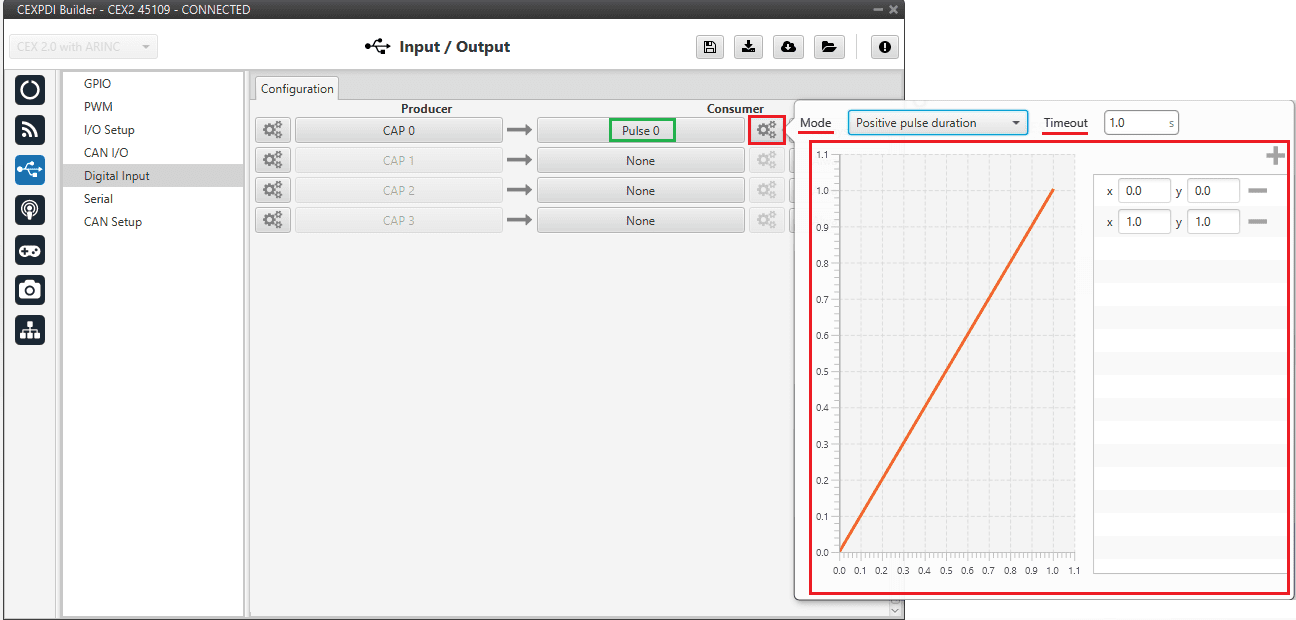
Digital Input panel - Pulse
In the pop-up window, users will find the following options for configuration:
Mode:
Positive pulse duration: The period of the pulse is obtained. It takes the time in ‘High’ state.
Negative pulse duration: The period of the pulse is obtained. It takes the time in ‘Low’ state.

Positive/Negative pulse duration
Positive duty cycle: The duty cycle of the pulse is obtained. It takes the time in ‘High’ state.
Negative duty cycle: The duty cycle of the pulse is obtained. It takes the time in ‘Low’ state.
Positive/Negative duty cycle
Time out: This defines the time to consider that no signal is received.
Function: Here the user can customise a function to handle the values. Normally, a function is set with the points [0,0] and [1,1], so no transformation is applied, input = output. However, the user can configure it as desired.
Example
Let’s imagine that First rising edge has been selected as the wrap option in Producer and the pulse that CEX has to read is a square signal with a period of 2 seconds and a duty cycle of 25% (see image below).

Signal generated
On the other hand, if Positive pulse duration is selected as Consumer and it is configured as in the previous image (Digital Input - Pulse), the value obtained in the variable Captured pulse (Captured pulse 1 in the following example) will be 0.50s, this is because it is the period of the “Positive pulse” of that pulse.
However, if Positive duty cycle is selected as Consumer, the value obtained in the variable Captured pulse (Captured pulse 2 in the following example) will be 0.25, this is because it is the positive duty cycle of that pulse.
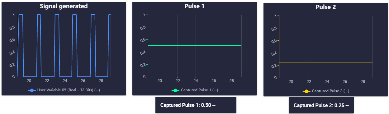
Digital Input example
Serial
CEX can use up to three serial peripherals (SCI A, SCI B and SCI C). Serial ports A, B and C parameters can be edited in this menu to fit the serial protocol requirements.
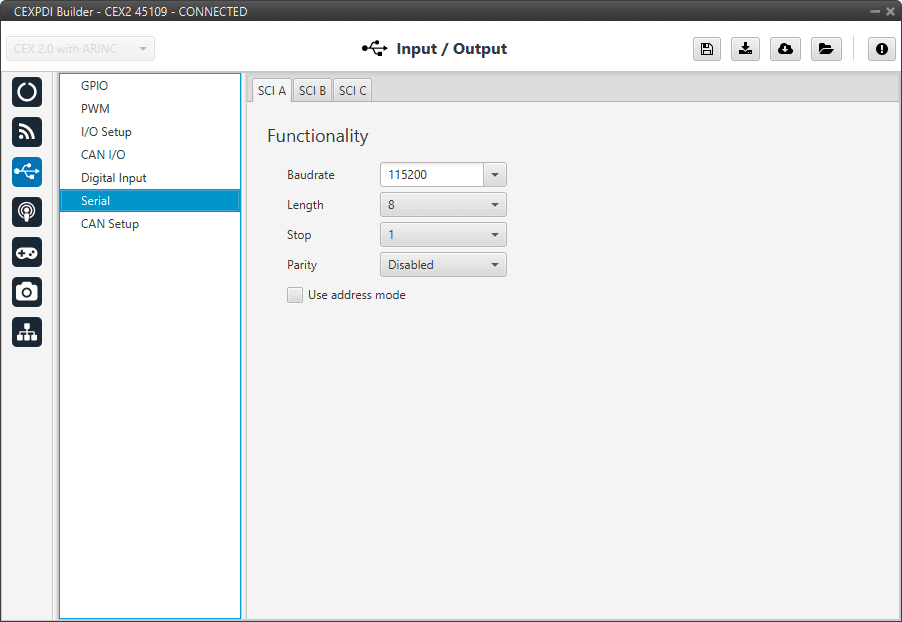
Serial panel
Baudrate: This specifies how fast data is sent over a serial line.
Length: This defines the number of data bits in each character: 4 to 8 bits.
Stop: Number of stop bits sent at the end of every character: 1, 1.5, 2.
Parity: Is a method of detecting errors in transmission. When parity is used with a serial port, an extra data bit is sent with each data character, arranged so that the number of 1 bits in each character, including the parity bit. Disabled, odd or even.
Use address mode: 9-bit data framing uses the bit typically associated with parity error detection to identify address messages. Sent serial data that does not have the address bit set will be ignored (unless the device had previously identified an address message associated with it). This option can be disabled or enabled.
Note
SCI A corresponds to port RS232-A, SCI B to port RS232-B and SCI C to port RS485-C.
CAN Setup
In this screen users can configure the baudrate and the reception mailboxes of each CAN Bus.
Since CEX is going to receive data on the CAN Bus, it is mandatory to configure a certain number of mailboxes to store that data until CEX reads it.
A mailbox can be configured for multiple CAN message IDs as long as the mask is configured correctly and these messages are sent spaced out with enough time between them to allow the high priority core to read each one individually. More information on masks can be found in How to calculate a mask - FAQ section of this manual.
Warning
Since CEX PDI Builder allows up to 32 mailboxes, users should make sure to leave at least one mailbox free for transmission (TX).
If any mailbox is full and another message arrives, the new message is discarded.
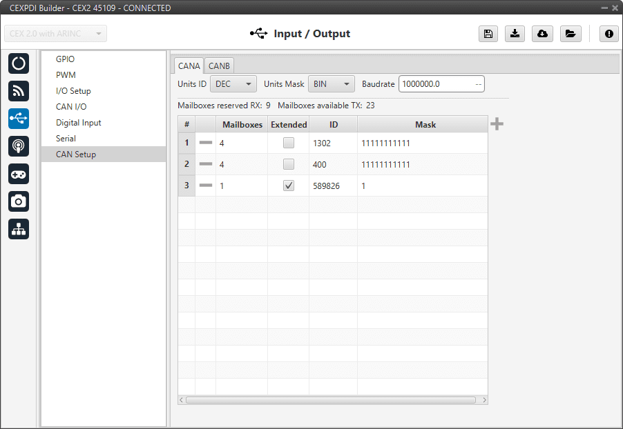
CAN Setup panel
More information about mailboxes can be found in the Mailboxes - Input/Output section of the 1x PDI Builder user manual.